WiFiMCU is developed based on EMW3165 by Headquarters EMW3165. Run the Lua script directly; operate hardware resource; achieve product prototypes.
EMW3165 is a low-power embedded WiFi module, which is developed by the Shanghai MXCHIP Technology Co., Ltd. It incorporates a WiFi RF-Chip and a microcontroller based on STM Cortex-M4. The WiFi module includes a "self-hosted" WiFi network library and application components.
In addition, it also provides 2 MBytes of out-chip flash, 512 KBytes of on-chip flash, 128 KBytes of RAM, and rich peripheral resources.
The WiFiMCU hardware offers the following features:
- STM32F411CE Cortex-M4 microcotroller 100MHz clock
- 2 MBytes of SPI flash
- 512 KBytes of on-chip flash
- 128 KBytes of RAM
- 17 GPIO Pin
- 11 PWM
- 3 UARTs
- ADC(5)/SPI(1)/I2C(1)/USB(1)
- SWD debug interface
- Broadcom IEEE 802.11 b/g/n RF-Chip supporting 802.11 b/g/n
- WEP,WPA/WPA2,PSK/Enterprise
- 16.5 dBm@11b,14.5 dBm@11g,13.5 dBm@11n
- Receiver sensitivity:-87 dBm
- Station,Soft AP and Station+Soft AP
- CE, FCC suitable
- Operation Temperature:-30℃ ~ +85℃
Detailed information about the EMW3165 device you will find in the EMW3165 Data Sheet.
Some external components enhance the EMW3165 device to the WiFiMCU module shown in the following figure.
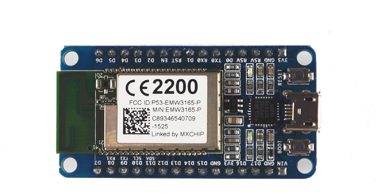
The schematic of the WiFiMCU module here shown separately can be found in the WiFiMCU repository

Here are some remarks going from top-left to bottom-right.
A Silicon Labs CP2102 USB-to-UART Bridge Controller provides USB to the PC while communicating via a simple serial protocol. Actual Windows versions (Windows 7 and above) should install the required driver automatically. If the installation fails you can install by hand following the WiFiMCU_Tutorial from WiFiMCU Repository or instructions, such of those from Pololu, for example.
You can power the WiFiMCU module by USB directly or over the pin VIN. The supply voltage of 3.3 V used by the EMW6135 module is converted internally. One LED is connected to VDD3V3 (3.3 V) and is an indicator for powering the module. A second LED is connected to PA4 of the EMW3165 device respectivally D17 of the WiFiMCU module and serves as user LED.
The next table supports a better orientation between the EMW3165 pinning and the GPIO index used in application programs:
| EMW3165 pin | GPIO index | Alternative Function | Description |
|---|---|---|---|
| PB2 | D0 | GPIO/BOOT | WiFiMCU would enter into Bootloader Mode, if D0 goes to LOW |
| D1 | GPIO/PWM/ADC | ||
| nRST | D2 | GPIO | |
| PA0 | D3 | GPIO/PWM | |
| PC13 | D4 | GPIO | |
| PA14/SWDCLK | D5 | GPIO | SWD Flash Programming Pin: swclk |
| PA13/SWDIO | D6 | GPIO | SWD Flash Programming Pin: swdio |
| D7 | GPIO | ||
| PA10/RX1 | D8 | GPIO/PWM | Uart1 rx pin: RX1 |
| PB6/TX1 | D9 | GPIO/PWM | Uart1 tx pin: TX1 |
| PB8/SCL | D10 | GPIO/PWM | I2C interface: SCL |
| PB9/SDA | D11 | GPIO/PWM | I2C interface: SDA |
| D12 | GPIO/PWM | ||
| D13 | GPIO/PWM/ADC | ||
| D14 | GPIO/PWM | ||
| D15 | GPIO/PWM/ADC | ||
| PB0 | D16 | GPIO/PWM/ADC | |
| PA4 | D17 | GPIO/ADC | A LED is connected on WiFiMCU board |
Two keys control the behavior of the WiFiMCU module. Pressing the RESET key resets the microcontroller. Pressing the EASYLINK key (in the documentation it is named BOOT) during power up or reset activates the bootloader for programming the firmware.
All IO pins of the EMW6135 module are available on external pins and have 3.3 V level. If you want to connect these with 5 V logic you need level shifters.
All what we need for a first operation of the WiFiMCU module is an USB connection to the PC. This connection powers the WIFIMCU module. The serial interface is used for firmware and/or program download.